Printed circuit boards (PCBs) and cable assemblies serve distinct yet complementary roles in electronic products, each vital to the functionality and reliability of the system.
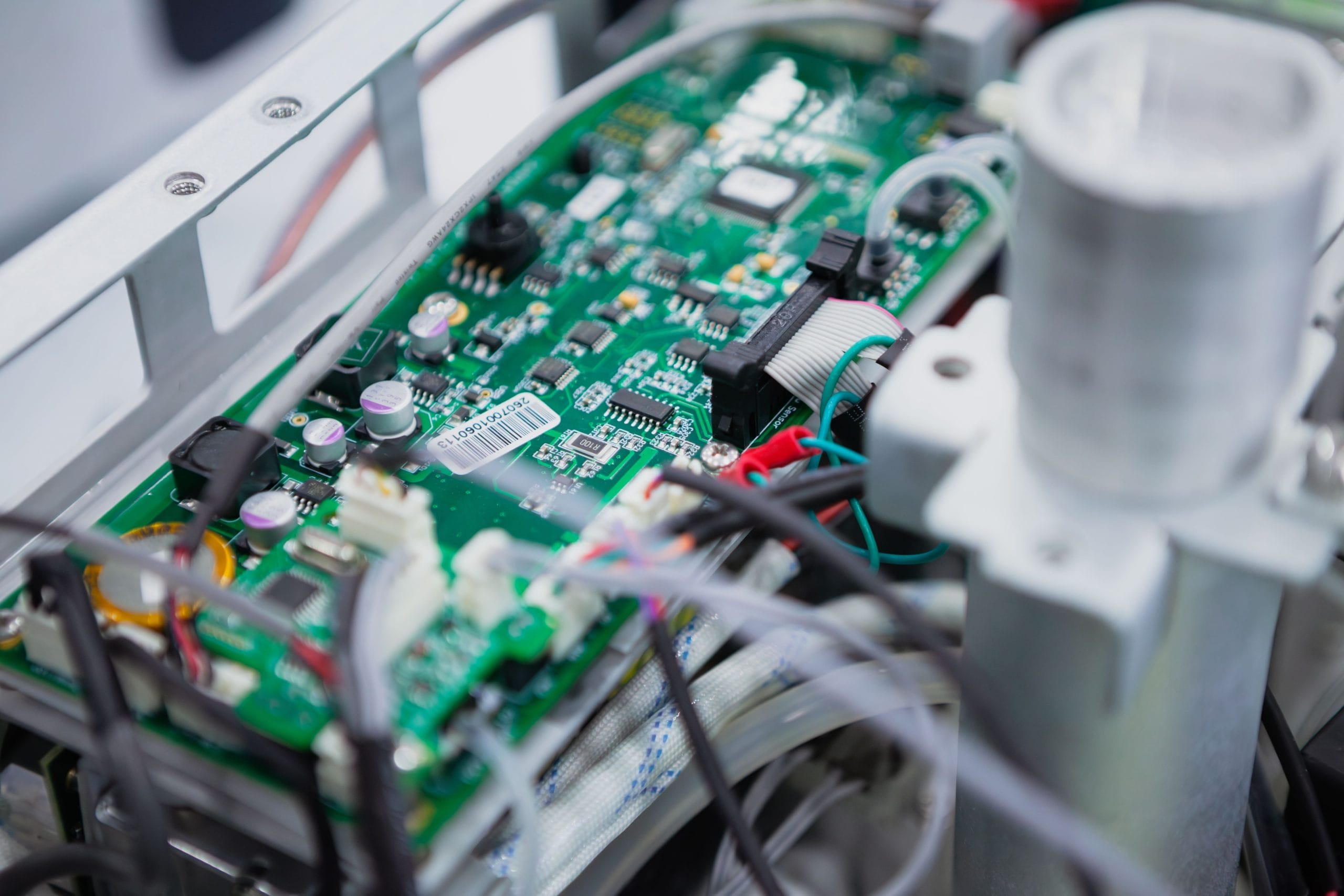
PCBs act as the control hub, hosting and interconnecting electronic components through a carefully designed network of conductive pathways. They manage the internal flow of electrical signals, powering and coordinating the operation of printed circuit board components like microprocessors, sensors and capacitors.
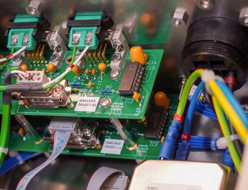
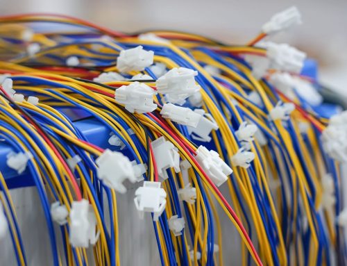
Cable assemblies serve as the bridge between separate parts of the system, facilitating the transmission of signals and power. Whether linking multiple PCBs within a device, connecting to external peripherals or routing signals across different modules, cable assemblies ensure seamless communication and energy transfer across the entire system.
Together, they form the backbone of electronic devices. But how do they work — separately and together?
How does a printed circuit board work?
At the heart of most electronic devices is the printed circuit board, a carefully designed platform that connects and supports electronic components.
The printed circuit board design determines how electrical signals flow between these components, enabling the device to perform specific functions. Layers of conductive tracks are etched onto a non-conductive substrate, connecting various printed circuit board components like resistors, capacitors and microchips.
To understand how printed circuit boards work, think of them as the ‘brains’ of electronic devices, directing signals precisely to ensure optimal performance. Once the printed circuit board assembly process is complete, the PCB is tested to guarantee functionality before being integrated into the final product.
How does a cable assembly work?
Whilst PCBs manage signal distribution within a device, cable assemblies play a vital role in connecting different printed circuit boards or linking external components to the system.
A cable assembly bundles multiple wires together, protecting them with robust insulation to ensure durability and organisation. This not only simplifies installation but also enhances performance by preventing signal interference. The versatility of cable assemblies makes them essential for various applications, from transmitting power in large industrial systems to enabling data flow in compact consumer electronics.
How printed circuit boards work together with cable assemblies
The synergy between printed circuit boards and cable assemblies is essential for the functionality of electronic products. These components work in tandem to enable the efficient flow of power and signals, connecting internal systems and external peripherals. This collaboration involves meticulous coordination throughout the stages of design, assembly and testing, ensuring optimal performance and durability.
1. Design and component selection
The journey begins with detailed planning. Engineers focus on printed circuit board design, ensuring the layout facilitates efficient signal flow whilst also accommodating the requirements of the cable assemblies.
Compatibility between the PCB and cables is paramount, necessitating careful consideration of connector types, pin configurations and signal or voltage requirements. For instance, connectors must be chosen to match the PCB header types, whilst shielding within the cable might be included to protect against electromagnetic interference (EMI).
Ground planes, impedance control and proper signal routing on the printed circuit board help maintain signal integrity, which is critical when transmitting high-frequency data. At the same time, the selection of printed circuit board components and cable materials ensures the system can withstand environmental factors like temperature fluctuations, moisture or mechanical stresses.
Durability and reliability are also addressed through robust material choices, such as flame-resistant cables and heat-resistant PCB substrates. This stage ensures both the printed circuit board assembly and cable assembly will be engineered to perform reliably under the specific demands of the application.
2. Assembly
Once the designs are finalised, manufacturing moves into the assembly phase. The printed circuit board assembly process involves mounting components onto the PCB using either through-hole or surface-mount technology (SMT).
Through-hole components provide mechanical stability and are typically used for high-power or high-reliability applications, whilst SMT enables compact designs by mounting components directly onto the PCB surface. Each method must consider how the printed circuit board components will connect to the cable assembly, ensuring alignment and secure connections.
Simultaneously, the cable assembly is manufactured, with attention to proper insulation, strain relief and termination techniques to ensure both reliability and ease of integration. Integration might involve soldering cables directly onto the PCB, connecting them via headers or sockets, or using custom connectors tailored to the device.
During this stage, physical tolerances are critical. For example, cables must fit precisely into their designated spaces without excessive bending or stress, which could lead to performance degradation over time. Proper routing and strain relief within the cable assemblies also play a significant role in protecting connections and maintaining durability. Additionally, thermal management strategies, such as heat sinks on the PCB or heat-resistant cable insulation, are implemented to prevent overheating and ensure long-term reliability.
3. Testing
Testing is a vital step in ensuring the printed circuit board assembly and cable assembly work together seamlessly. Engineers evaluate how the printed circuit board works alongside the connected cables, checking for issues like signal loss, impedance mismatches or EMI. Tools such as oscilloscopes can be used to verify signal integrity and electrical continuity across the entire system.
Physical testing is also conducted to assess the reliability of the connections under real-world conditions. For example, cable assemblies might undergo pull-strength tests to ensure connectors can withstand mechanical stresses, whilst PCBs are subjected to thermal cycling and vibration testing to validate the robustness of soldered joints and component placements. These rigorous tests are critical for catching potential weaknesses and ensuring both the printed circuit board assembly and cable assembly meet performance standards.
One electronics manufacturer for both PCB and cable assemblies
In most electronic products, printed circuit boards and cable assemblies are directly connected, making their integration vital to the device’s success.
Partnering with a supplier that can manufacture and test both assemblies offers several advantages. By consolidating the supply chain, you ensure compatibility, streamline production and reduce the risk of miscommunication between separate vendors.
EC Electronics is a leading UK and European electronics manufacturing services provider and a specialist printed circuit board and cable assembly manufacturer. We have over 40 years of experience delivering quality PCB assemblies and custom cable assemblies to customers across a range of markets.
If you are looking for a trusted partner to manufacture PCB and cable assemblies for your electronic product, we can help.
We are continuously working to industry best practices, including IPC/WHMA-A-620 Class 3 for cable assemblies and IPC-A-610 Class 3 for PCB assemblies. EC Electronics is also officially certified to EN ISO/IEC 80079-34:2018 standards in line with IECEx and ATEX Directive 2014/34/EU, ensuring all electronic equipment we manufacture for potentially explosive environments is subject to rigorous testing.
This commitment to quality ensures your products always meet the highest standards and performance.
Email us at sales@ecelectronics.com to learn more.

