Skip to content

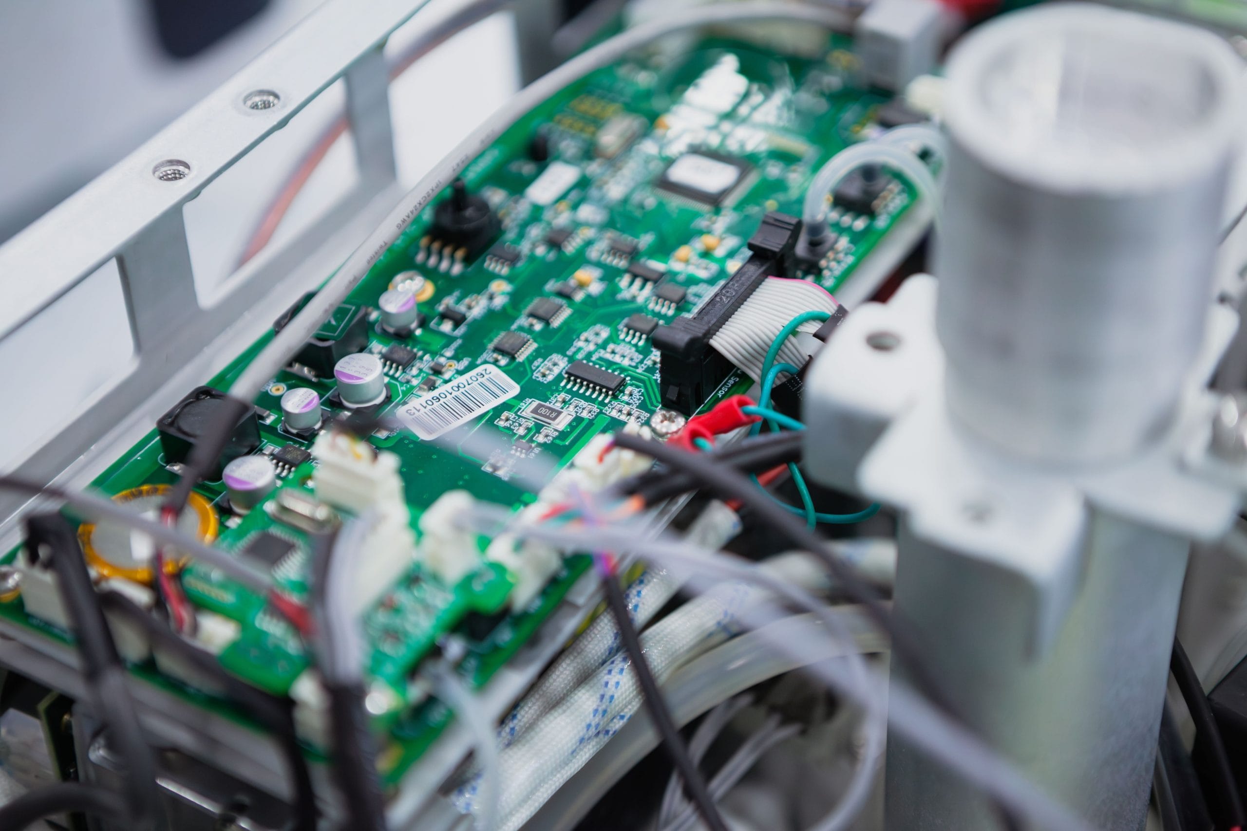
Printed circuit boards (PCBs) and cable assemblies serve distinct yet complementary roles in electronic products. Specifically, each element ensures optimal system functionality and reliability.
PCBs act as the primary control hub. They interconnect components through a carefully designed network of conductive pathways. Consequently, they manage the internal flow of electrical signals across microprocessors, sensors, and capacitors.
Meanwhile, cable assemblies bridge separate parts of the system. They facilitate the smooth transmission of signals and power between modules. Whether linking multiple boards or connecting external peripherals, cable assemblies ensure seamless communication.
Therefore, combining PCBs and cable assemblies effectively forms the backbone of modern electronics. How do these technologies work together?
How does a printed circuit board work?
At the heart of most electronic devices sits the printed circuit board. This platform connects and supports various components.
The board layout determines how electrical signals flow across pathways. Furthermore, etched conductive tracks connect resistors, capacitors, and microchips on a non-conductive substrate.
Think of printed circuit boards as central signal directors. They route electricity precisely to ensure peak operational performance. Once assembly ends, technicians test the PCB before final product integration.
How does a cable assembly work?
While PCBs manage internal signals, cable assemblies connect separate boards and peripherals.
A cable assembly bundles multiple conductors within robust insulation. Consequently, this arrangement simplifies installation and prevents signal interference. Moreover, cable assemblies power industrial equipment and connect compact consumer devices effectively.
Guidelines for combining PCBs and cable assemblies
The synergy achieved when combining PCBs and cable assemblies remains essential for electronic products. These systems work in tandem to route power efficiently across modules. Furthermore, successful integration requires meticulous coordination across design, assembly, and testing phases.
1. Design and component selection[/fusion_text]Engineering begins with detailed planning. Specifically, teams design PCB layouts to support physical cable requirements.
Connector compatibility remains paramount. For instance, connectors must match header types, while shielding protects against electromagnetic interference (EMI). To verify general assembly criteria, consult official IPC industry standards.
Proper signal routing and impedance control maintain electrical performance. Meanwhile, flame-resistant cables and heat-resistant substrates handle environmental stresses.
2. Assembly
Engineering begins with detailed planning. Specifically, teams design PCB layouts to support physical cable requirements.
Connector compatibility remains paramount. For instance, connectors must match header types, while shielding protects against electromagnetic interference (EMI). To verify general assembly criteria, consult official IPC industry standards.
Proper signal routing and impedance control maintain electrical performance. Meanwhile, flame-resistant cables and heat-resistant substrates handle environmental stresses.
After finalizing designs, production enters the assembly phase. Technicians mount components onto PCBs using surface-mount technology (SMT) or through-hole methods.
Through-hole parts offer mechanical stability for power systems, whereas SMT creates compact layouts. Furthermore, technicians build cable assemblies with strain relief and proper insulation.
During integration, managing physical tolerances prevents wire bending. Additionally, thermal management tools prevent overheating.
3. Testing
Rigorous testing confirms that assemblies work together seamlessly. Engineers evaluate electrical performance using oscilloscopes to check for signal loss.
Furthermore, physical testing verifies mechanical reliability under stress. Cable assemblies undergo pull-strength checks, while PCBs endure thermal cycling. Consequently, these procedures confirm that products meet quality standards.
One electronics manufacturer for both PCB and cable assemblies
In most electronics, hardware integration requires seamless manufacturing.
Partnering with a single supplier yields significant operational advantages. By consolidating production, you ensure full compatibility and streamline workflow.
EC Electronics operates as a leading European electronics manufacturing services provider. We bring over 40 years of experience delivering custom assemblies.
We adhere strictly to IPC/WHMA-A-620 Class 3 and IPC-A-610 Class 3 standards. Furthermore, EC Electronics maintains certification to EN ISO/IEC 80079-34:2018 for hazardous environments.

Email us at sales@ecelectronics.com to discuss your next project.